Head Rotation - Axes & Directions
This application note describes the use and setup of rotary tables and heads for 4 and 5-axis machining.
Pitch/Yaw of the tables or Swivel/Tilt of the head enable cutting complex 3-D contours like those found in molds and dies, aerospace and automotive, and many more.
The angles A, B, C designate rotations about the X, Y, and Z axes, respectively.
Note that all standards define the positive direction (i.e., increasing angle) as CCW rotation of the cutting tool.
This direction is easily found by holding your right hand with your thumb points in the positive direction of the linear axis and then your curled fingers show the positive rotary direction.
For dual rotaries the name of the second axis is based on its orientation when the first axis is at zero.
Note that the direction of any axis is defined as the direction of the tool (regardless whether the tool or the table moves), therefore the direction of rotary tables is reversed - so use your left hand instead.
Head Rotation - Axes & Directions
There are a few ways to build 4 and 5-axis machines:
For more info visit:
Modern Machine Shop
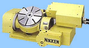
The advantage of rotary tables is that they can easily be installed when needed.
Note that rotary table B is usually used on horizontal machines, mainly for cutting heavy parts from different sides.
Rotary table A is usually used with vertical machines to cut cams and roller dies.
Dual rotary tables are usually AB for horizontal machine and AC for vertical machine, but other configurations are used as well.
|
|
|
For vertical machines the head can be tilted by B-axis, which turns about the Y-axis.
The tilted head reduces the rigidity less than any other head.
Automatic tool changer can be used same as with 3-axis machines.
Adding 5th axis A enables tilting the tool about the X-axis.
This BA head is less intuitive to move manually than a CA head.
|
|
|
CA and CB heads are same heads with a different setup. When C=0, CA is set so that the 5th axis turns about X-axis and CB is set so that the 5th axis turns about Y-axis.
CA/CB heads can be built in a few ways described below.
When A (or B) is zero the tool is aligned with the Z-direction, which is a singularity (see below).
If we cut a shape on a cylindrical surface then C-axis can be set once and the cutting is done by XYZA. In this case A may cross thru zero from positive to negative.
But when cutting a spherical surface, if you imagine the globe, A-zero may only occur at the poles, which are dead ends. To cut a shape like a latitude circle around the globe, C has to turn 360 degrees.
If C-axis has limits it requires frequent unwinding. The programmer has to plan ahead how the part will be positioned on the table and where to introduce unwinding.
With a limitless C-axis some controls have automatic electronic unwinding that doesn't generate any motion. (It is unlikely and undesirable that the control will do mechanical unwinding automatically).
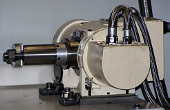
C is mounted on Z, A is mounted on C, and the spindle is mounted on A.
Electrical cables are running between the axes and therefore C-axis travel is limited.
This is usually an attachment to 3-axis VMC and intended for light jobs.
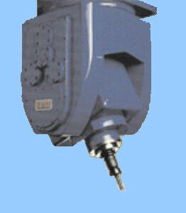
The spindle and A-axis are driven thru C-axis and no motor is mounted on the head; consequently no cables are running between the moving members and C is limitless. However, the differential mechanism makes A move when C moves. This can be compensated by the post-processor but if it is not done internally by the control then:
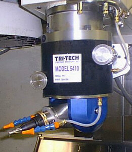
Differential CA head attached to a Fadal VMC
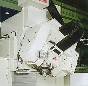
Nutating head has advantages over other CA heads because it is compact, has no motors on the head, and is more rigid.
The first axis is C but the second one (A) is inclined up to 45 degrees.
The virtual A (which is the true orientation of the tool) can move to both positive and negative directions up to twice the inclination.
For example. if the inclination is 30 degrees the virtual A range is +-60 degrees.
The motors for the spindle and both C and A are on the machine and the motion is transferred to them by hollow shafts and gears.
To move the virtual A (without changing virtual C) A and C move in tandem. Here are the positions at the extreme:
virtual  axis     axis
  A        A        C

  0        0        0
 max      180     -90
-max     -180      90
Since C compensates for A, if C is not limitless a significant amount of its travel is lost.
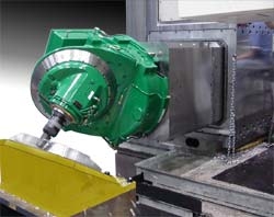
Nutating Head on an Ingersol HMC
A CA head is mostly used for vertical and gantry machines while CB head is used for horizontal machines.
The head with rotary axes provides tilt and swivel for the cutting tool.
The difference between CA and CB heads is how the zero position is set.
CA Head Coordinates
The advantages of 5-axis machine are:
There are some disadvantages though:
The perfect orientation mechanism will change the tool orientation without changing its location.
In such a case changing orientation doesn't require any linear move.
This is impossible to achieve because of mechanical constrains.
For A or B tilt there is a certain distance between the center of rotation (pivot) and the tool tip.
This is called pivot length. In some machines it is reduced to a small distance by a clever design.
However, tool length changes this length and therefore tool length setting must be accurate.
Note that for 3-axis milling incorrect tool length setting is compensated by the home setting and at worst it will change the depth of the cut. With rotary head incorrect tool length changes the shape as well. Just imagine a sphere cut with a CA head - its radius accuracy depends upon an accurate setting of the tool length.
For CA head X and Y each may also have a pivot length, either by design or because of misalignment (offset).
For BA head, B may have X offset and A has some distance from B-pivot. The total Z-pivot length is therefore affected by both tool length and A-axis orientation.
It is impossible to manually program or even edit a program for a 5-axis machine because:
With dual rotaries, fixture offset must be included in the part program produced by the post-processor but tool length works since it is just added to Z.
With CA head, fixture offset works okay, since the offsets are simply added to the machine zero, but tool length must be inserted in the program by the post.
The purpose of all machine tools is to move the tool in a programmed path, which is defined as a series of positions. For the part, a position is the position of the Tool Center Point (TCP).
If the finished part is programmed, we need to transform the coordinates of the TCP to the actual machine axes. These calculations are based on the programmed positions and the tool dimensions.
For 5-axis machine, TCP has 3 position-axes (XYZ) plus 2 orientation-axes (CA). The position axes locate the tool tip while the orientation axes set its orientation.
Jogging in TCP mode is a lot easier than moving each axis separately, since we control the position and orientation of the tool, not the machine.
A 5-axis machine tool has a complex relationship between the TCP and the actual axes.
The combined contribution of all axes to the position of the TCP is called Kinematics.
Inverse Kinematics is the process in which the control calculates the position of each axis for a given TCP.
Note that CA head has two solutions for the inverse-kinematics equations, that is, for the same position and orientation, two sets of axis data can be evaluated, for instance, C=45, A=30 is the same orientation as C= -135 , A= -30.
Singularity (also called degenerate or dead point) is an orientation, in which the first rotary axis cannot control the orientation anymore.
For a CA head, when C=0 A turns about X-axis in the YZ plane. When A=0 the tool orientation is down (-Z), same as in a 3-axis machine.
This orientation is a Singularity since moving C does not change the orientation (the tool turns about itself).
Unfortunately, this orientation is in the useful working area of the CA head.
For a BA head, the Singularity occurs when A=+-90 (+- Y-direction).
This orientation is rarely needed and in the normal cutting area we are far from Singularity.
While moving the orientation axes, crossing a Singularity is not a problem. Moving close to it is a difficult task.
For a CA head, C and A are actual axes, that means that the programmer or the post processor has to solve the singularity problem.
Close to a Singularity, the post would generate a rapid change of up to 180 degrees in C-axis.
Note that this is a Nature's Law and not any deficiency of the control or the post.
The Singularity phenomenon is hard to explain, even while watching the machine.
The tool tip has a known distance from the A-pivot, called pivot length. If we express angles in micro-radians then every inch of tool length generates 1 micro-inch for 1 micro-radian.
One thousandth of a degree is about 17.5 micro-radian, therefore, for a 20-inch (500 mm) pivot length, every 0.001-degree of error generates 0.35 thousandth (9 micron) position error.
While these numbers seem small, remember that the machine accuracy is 5-10 times worse than the measuring system. In addition, it is very difficult to build the CA head such that the C axis is absolutely perpendicular to the Z-axis and the C axis and the spindle axis are perfectly parallel.
And don't forget the thermal expansion.
It is possible to measure the angular deviation and compensate for it by software but that makes the Singularity rear its ugly head.
The problem now is that the control has to calculate corrected C and A and:
Many users of 5-axis machines use this technique - C and A are set to the desired orientation and clamped, then the machine runs by a regular 3-axis program.
This method is useful for cutting in odd orientations or avoiding ball nose cutter cutting on its center.
But there are some drawbacks:
The standard NCPlus can handle up to 8 axes, rotary and linear.
To use additional features for tool orientation there are TCP extensions that are sold separately as TCP files, based on the machine kinematics.
The TCP files are compact and fast. With a 300 MHz Pentium, a 5-axis transformation takes additional 10-15 micro-seconds, which means that block processing time is 35-40 micro-seconds.
Without TCP extensions the machine is a 5-axis regular machine.
Each axis is independent. Each axis moves as programmed. To achieve vector feed at the tool tip, feed should be programmed in inverse time (g93, feed/length), which should be programmed in every line. Note that for same feed, the F-number is different from line to line, depending on the length of the linear move. Jogging is limited to the actual machine axes.
With the appropriate TCP file you get:

This standard feature is independent of TCP extensions.
Limitless is defined in line n19 of the machine data. For Example, axis C:
n19 C1 \program in DegreesThis command sets the axis limits internally to about +-1,000,000,000 encoder counts.
Note that when using this axis as a linear one the feed in DPM is the feed in mm/min, therefore, if feed is programmed in IPM, the actual DPM is 25 times the programmed feed.
A limitless rotary axis can optionally be programmed in DPM (or RPM) instead of position. If set, it is programmed by M-functions similar to M3/4/5. The mode can be switched any time without losing position.This standard feature is independent of TCP extensions.
In some cases a CA head has a differential drive, so that both motors are mounted on the stationary part of the head.
The driving and driven axes in a differential system, as well as the differential ratio, are entered in line n16.
Example (the ratio is 5/9):
n16 a=5/9 c
C is the first axis in the differential chain, which is denoted by C=0.
A is the driven axis and it is moved opposite to the excess motion generated by C:
A= 5/9 * CThe sign of the fraction should be positive if positive motion of C results in negative motion of A (without compensation).
Nutating head transformation is included in its TCP extension. Both CA and CB are supported.
It converts regular C-A or C-B orientation to the actual nutating axes.
The head axes can move independently, or with transformation, or with full 5-axis RTCP.
To select head transformation only use H2. H2 can be set as the default if so desired.
Note that when virtual A is close to its limit the transformation and the mechanical accuracies are compromised.
C is usually set as a limitless axis.
H5 is the TCP mode. The mode is displayed at the top line.
H5 can be programmed in any block before or after axis data or toggled in Manual and Set-Home by F5.
H5 is canceled by H0.
H is set to zero when starting a program from the beginning and after M2.
Reset doesn't reset H.
While in TCP mode the Cartesian coordinate system is attached to the work-piece.
With rotary table - when all rotary axes are at zero that is the regular XYZ system, but when one or more moves away from zero the coordinates move with them.
With rotary head XYZ are always the machine axes.
This makes it possible to change the orientation of the tool as it cuts while maintaining the programmed xyz path and feed.
A TCP program should have H5 before the first TCP move.
The post-processor should assume zero offset between the rotary axes, and zero offset for the work piece.
The rotary axes should be used for orientation without affecting the XYZ coordinates.
Feed should be given in ipm or mm/min, same as with a regular 3-axis program.
G93 is not required.
Tool length compensation is done by NCPlus.
Tool radius compensation must be included in the tool path, unless the post produces ijk vector (compensation direction) for each block (version 6 only).
Fixture offset, zero shift (g52), rotation, and scale can be used.
To move in the direction of the machine axes the program can switch to H0, or G100 (single shot) can be used. In both cases incremental data should be use, however, with g100 the data is always considered incremental.
g100 g1 z-1 f10
g100 z1 f20
For the drilling canned cycles xyz position is in the TCP coordinates and the drilling is in the tool direction.
G0 x_ y_ z_ g81 g91 r-.2 z-.5 f80
x_ y_ z_          \absolute
. . . .
g80
Positioning command first calculates the target position and then moves all axes simultaneously to that target. Tool-tip doesn't follow a straight line and an endless rotary axis selects the shortest direction to the target.
Interpolation command divides any motion into knots, either one block or no longer than 1 mm, and does the transformation per each knot.
If XYZ motion is programmed the feed applies to the tool-tip and all axes move as fast as needed up to their feed limit. The displayed feed is that of the tool-tip.
If rotary axes only are programmed (in TCP) they move at their feed limit, and the displayed feed is zero.
Jogging is programmable and can be set as desired. Usually it is set as follows:
Jogging of XYZ (or using of MPG) is in the tilted/rotated coordinate system. In case of CA head these are the tool coordinates (Z moves in the tool direction).
Jog-zero doesn't work (there is no zero to the tool coordinates).
In case of rotary tables these are the work-piece coordinates. Jog-zero does work.
Note: Jogging of an axis may cause small deviations in other virtual axes. This doesn't happen in programmed moves or incremental jog.
The Home (fixture offset) for a specific work can be set anywhere, but with rotary tables it is desired that the center of the work-piece will be close to the center of rotation.
Home setting for rotary axes is disabled, except for the second rotary table (5th axis), which can be used to align the work-piece with the machine axes.
Note: For rotary tables, if the rotary axes are not at zero, use H5 while setting the Home (fixture offset) for xyz.
To set Z-Home and tool length: